Flow Control Valve Schematic Symbol
Valve symbols piping pump symbol vacuum mechanical engineering used process diagram flow chart types abbreviation drawings instrumentation standard plant sign Valves different Design elements
Hydraulic flow control valve symbols
Valve flow control testing symbol hydraulic pump What’s the difference between hydraulic circuit symbols? Flow control hydraulic valves pressure compensated circuit symbology controls
Pneumatic symbols circuit valve position explained solenoid spring return double flow actuated path
Flow control valve testingHydraulic flow control valve symbols Fluid power systemsFlow control valve hydraulic pressure compensated schematic troubleshooting valves.
The most common control valve symbols on a p&idSymbols valves Schematic hydraulic valve control directional drawing engineering spring mechanical symbol parts equipment diagram pump flow pneumatic solenoid valves reservoir machineMachine drawing: rotary four way valves.

Direction drawing symbols control way valves four hydraulics actuation rotary methods machine mechanical
Symbols flow valve valves chart engineering piping chemical diagram process basic instrumentation tanks mechanical control bmp instrument read hydraulic butterflyPneumatic circuit symbols explained |library.automationdirect Symbols valve solenoid valves drawing schematic symbol pid process diagram piping instrumentation connexion developments actuators control equipment represent used chooseDesign elements.
Fluid valves visio pneumatic mechanical conceptdraw hydraulic stencils operated direction regulator reducing bypass hydraulicsMechanical engineering Process flow sheets: flow chart symbolsStandard process flow diagram symbols and their usage.

Pressure control valve- types , symbol ,application
Flow control valve symbols hydraulic orifice symbol its basic form just hyd principValve symbols valves flow process diagram symbol engineering gate control instrumentation piping pump drawing simboli mechanical standard simbolo check air Hydraulic flow control valve symbolsInterior design. piping plan — design elements.
Pressure reducing pid commonlySymbols engineering valve drawing assembly mechanical pdf elements meanings valves pneumatic their diagram books used hydraulic getdrawings spring conceptdraw page1 Control fluid power systems discrete symbols schematic system diagram components represent fluids pumpsSimbol instrumentation piping actuator developing common.
Hydraulic flow control valves – hydraulic schematic troubleshooting
Hydraulic machinedesign circuits system commonly depictFlow control valves Hydraulic flow control valve symbol symbols basic orifice form its just valvesPiping & instrumentation diagram, p&id – process flow systems.
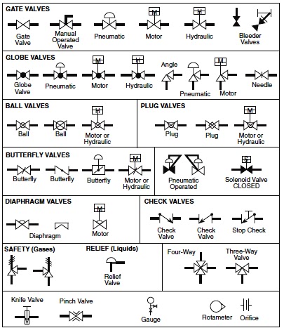
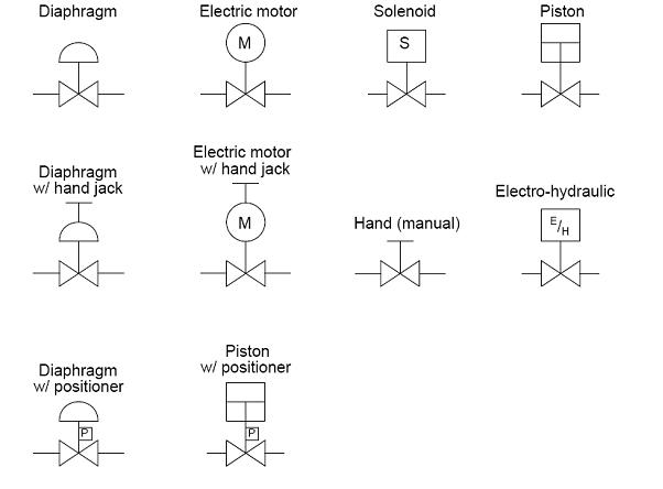
Types of valves, their functions and symbolsValve symbols valves drawing symbol hydraulic schematic piping elements check mechanical line relief pipe pressure gate drawings plumbing engineering plan Common p&id symbols used in developing instrumentation diagramsP&id process diagram, piping, symbol, abbreviation, equipment, pump.


Hydraulic Flow Control Valves – Hydraulic Schematic Troubleshooting

Types Of Valves, Their Functions And Symbols - Engineering Discoveries

Pressure Control Valve- Types , Symbol ,Application

Machine Drawing: rotary four way valves
Common P&ID symbols used in Developing Instrumentation Diagrams

Design elements - Valves | Valve symbols | Design elements - Fluid

Pneumatic Circuit Symbols Explained |Library.AutomationDirect

Hydraulic flow control valve symbols